Electrical Safety
1. Temperature Monitoring
The Charge Controllers have internal temperature sensors for the housing, ambience and relay. They activate an external fan or heater, reduce charging current or switch it off completely depending on the temperature or vehicle condition. In the backend, the manufacturer can set the threshhold values that activate the different functions.
| Function | Threshhold setting | Additional notes |
|---|---|---|
| Heating | VentHeatingTempThr | consists of 2 values, lower one activates heating |
| Fan | VentHeatingTempThr | consists of 2 values, higher one activates fan |
| Current reduction | TempReduceThreshold1 | must be lower than TempStopThreshold2 |
| Current switch off | TempStopThreshold2 | must be higher than TempStopThreshold1 |
1.1. Fan or heating function
This setting enables activation of an external fan or heater via the auxiliary relay K2 (13/14) depending on the housing temperature or vehicle condition.
| Function | Setting | Additional notes |
|---|---|---|
| Fan or heater configuration on relay K2 | Off | Default |
| Status D | Ventilation requested by vehicle. | |
| Charging | ||
| If temperature threshold is exceeded only during charging | Ventilation | |
| When temperature threshold is exceeded | ||
| When temperature threshold is undershot | Heating |
| Location in Legacy Configuration Interface | Parameter/Setting | Value | Info |
|---|---|---|---|
| Manufacturer | Fan or heater configuration on relay K2 | Off | Default |
Status D | Ventilation requested by vehicle. | ||
Charging | |||
If temperature threshold is exceeded only during charging | Ventilation | ||
When temperature threshold is exceeded | |||
When temperature threshold is undershot | Heating |
2. Contactor monitoring (Weld Check)
The Weld Check of the CC612 and CC613 is a protective measure against electrical touch in accordance with IEC 61851-1 edition 3. It monitors whether voltage (or a 50 Hz signal) is running between N and L1 in between the entry and the exit in the contactor after the charging process is ended and the connection state to the car is changed from B to A (plug connection to the car is separated). The monitoring is not possible for the change from state C to B, because some US car types create a 60 Hz signal in between N and L1 in state B and would generate false positive monitoring results.
The digital input in connection with relay K2 can be used for monitoring the contactor and for switching the additional relay K2 (13/14):
| Function | Setting | Additional notes |
|---|---|---|
| Weld Check | Switch off | For the options '230V input' with and without PE testing (if available), L1 must be connected before the contactor. In both cases, contactor bonding detection occurs as soon as the vehicle is unplugged and not immediately when the contactor is opened. |
| Activate 'Opto 1 in' | CC613 only | |
| Activate contactor weld test input 230V without PE monitoring | ||
| Activate contactor weld test input 230V with PE monitoring | ||
| Use Opto C6/5 | CC612 only | |
| Use Opto C8/7 |
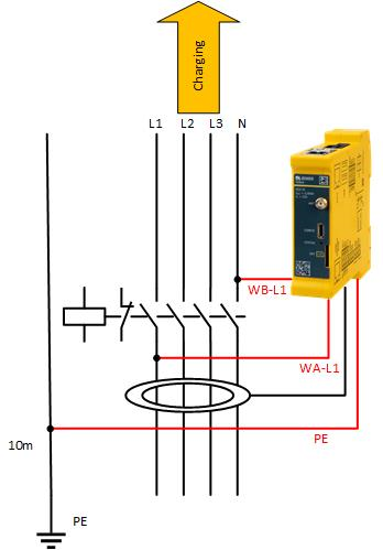
If you want to realize the contactor bonding monitoring with PE monitoring, please connect the contactor bonding monitoring and PE as follows:
If the contactor is welded, the additional relay K2 (13/14) can be closed additionally:
| Function | Setting | Additional notes |
|---|---|---|
| Contactor bonding monitoring output | Off | |
| Relay 13/14 (K2) | When enabled, the auxiliary relay is activated when the contactor is welded. If this function is activated on the CC1612, the RCD test output is not activated (normal operation), but the ExOut output selected here (e.g. for the use of a shunt release). |
3. Current limitation
Via the digital inputs In+ / IN- a current limitation of the DLM network (DLM Master) or of a single Charging Station (DLM Master/DLM Slave) can be made.
3.1. DLM network (DLM Master)
If energy management from an external input is active, then you can configure the Master in a DLM network to limit the current in the whole DLM network with an offset of your choice.
| Function | Setting | Additional notes |
|---|---|---|
| External Input 1 Status | Disable | Adds a configurable offset to the sub-distribution current limit, based on input 1. |
| Enable 'Opto 1 in' | CC613 only | |
| Use Opto C6/5 | CC612 only | |
| Use Opto C8/7 | ||
| External Input 1 Current Offset (L1/L2/L3) [A] | 0 / 0 / 0 | Offset to 'EVSE Sub-Distribution Limit' when external input 1 is high. Note: Currently only negative values are supported. |
| Polarity of external input 1 | Low-active | Changes the polarity of input signal 1. "High-active" does not change the polarity, "Low-active" inverts the signal. |
| High-active | ||
| External Input 2 Status (CC612 only) | Disable | Adds a configurable offset to the sub-distribution current limit based on input 2. |
| Use Opto C6/5 | CC612 only | |
| Use Opto C8/7 | ||
| External Input 2 Current Offset (L1/L2/L3) [A] | 0 / 0 / 0 | Offset to 'EVSE Sub-Distribution Limit' when external input 2 is high. Note: Currently only negative values are supported. |
| Polarity of external input 2 (CC612 only) | Low-active | Changes the polarity of input signal 2. "High-active" does not change the polarity, "Low-active" inverts the signal. |
| High-active |
3.2. Charging Station (DLM Master/DLM Slave)
With this setting you can enable or disable if a single charging station Master or Slave in a DLM network allows energy management from an external input.
| Function | Setting | Additional notes |
|---|---|---|
| Energy management from external input | Switch off | Enables energy management via floating contact input. |
| Enable 'Opto 1 in' | CC613 only | |
| Use Opto C6/5 | CC612 only | |
| Use Opto C8/7 |
4. RCD/SPD/MCB monitoring
Via the digital inputs In+ / IN- it is possible to tap a feedback signal from the RCD, SPD or MCB and thus to signal the Charge Controller that the RCD (FI) has dropped or that the SPD has tripped. The dropping of the RCD or the tripping of the SPD is also displayed in the error list, e.g. in the status of the web interface.
| Function | Setting | Additional notes |
|---|---|---|
| FI Enable | Off | Enables FI detection. It must be Off if no RCD is connected to the controller. For CC612 the opto input C6/5 is used. |
| On | ||
| SPD Config | Off | Enables the support of surge protection devices (SPD). The parameter must be set to "Off" if no SPD is connected to the controller. |
| On Opto 1 In (Normally Closed) | CC613 only | |
| To Opto 1 In (Normally Open) | ||
| To Opto 6/5 In (normally closed) | CC612 only | |
| To Opto 6/5 In (normally open) | ||
| To Opto 8/7 In (normally closed) | ||
| To Opto 8/7 In (normally open) | ||
| Automatic reclosure RCD | Off | Enables the automatic reclosure of the RCD. On CC612 the auxiliary relay output C3/4 is used. |
| On | ||
| RCD reclosure delay | 5...1800 (default 900) | Delay between two automatic reclosure attempts of the RCD in seconds. |
| RCD automatic reclosure attempts | 1...10 (Default 3) | RCD automatic reclosure attempts. |
| Coupling relay - RCD/LC common input | Disable | Use the common input from a monitoring relay to monitor RCD/LC. |
| Activate 'Opto 1 in' | CC613 only | |
| Use Opto C6/5 | CC612 only | |
| Use Opto C8/7 |
With RCD monitoring, an automatic reclosure can additionally be controlled via relay K2 (13/14). This is controversial in Germany, but relatively common in northern European countries.
5. Tilt Detection
There is a configuration parameter "Tilt detection" in the operator page with three options:
| Function | Setting | Additional notes |
|---|---|---|
| Tilt detection is enabled | On (Prevent) | when the charger is no longer tilted, no new transactions are allowed until after a reboot |
| On (Continue) | when the charger is no longer tilted, new transactions are allowed | |
| Tilt detection is not enabled | Off |
The default value is On (Prevent) When the charger is switched on the position at that moment is taken as reference. That position is considered the correct or non-tilted one (but only if it was not tilted before switching it off). If "Tilt detection" is on and if the inclination of the charger is equal or more than 20 degrees in any direction then: The transaction is terminated and charging is stopped completely. HMI goes red OCPP status notification "The ChargePoint is tilted." is sent. The inclination coordinates are saved in persistency. No new transactions are allowed while the charger is still tilted.
If the charger is moved back to the initial non tilted position: -- The inclination coordinates are removed from persistency. -- HMI goes back to green -- OCPP status notification "The ChargePoint no longer is tilted." is sent. -- In case of "On (Continue)" new transactions are allowed. -- In case of "On (Prevent)" no new transactions are allowed. HMI stays red. A reboot is required to allow transactions again.
If the charger is tilted and then rebooted, after the reboot HMI will stay red and no transactions are allowed. The inclination coordinates in persistency are used for this purpose.
Note that 20 degrees might seem too much. But experience has shown that lower values can lead to false positives since there can be some noise in the reading and also some error from the sensor. 5 degrees is too low. In the correct position one might already read 1 or 2 degrees, and just a light noise or small movement will trigger the tilted error.