Electrical Safety
We are currently preparing this section.
The content in this section is currently under review.
Fan or heating function
This setting enables activation of an external fan or heater via the auxiliary relay K2 (13/14) depending on the housing temperature or vehicle condition.
| Function | Setting | Additional notes |
|---|---|---|
| Fan or heater configuration on relay K2 | Off | |
| Status D | Ventilation requested by vehicle. | |
| Charging | ||
| If temperature threshold is exceeded only during charging | Ventilation | |
| When temperature threshold is exceeded | ||
| When temperature threshold is undershot | Heating |
Contactor monitoring (Weld Check)
The digital input in connection with relay K2 can be used for monitoring the contactor and for switching the additional relay K2 (13/14):
| Function | Setting | Additional notes |
|---|---|---|
| Weld Check | Switch off | For the options '230V input' with and without PE testing (if available), L1 must be connected before the contactor. In both cases, contactor bonding detection occurs as soon as the vehicle is unplugged and not immediately when the contactor is opened. |
| Activate 'Opto 1 in' | CC613 only | |
| Activate contactor weld test input 230V without PE monitoring | ||
| Activate contactor weld test input 230V with PE monitoring | ||
| Use Opto C6/5 | CC612 only | |
| Use Opto C8/7 |
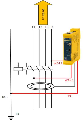
If you want to realize the contactor bonding monitoring with PE monitoring, please connect the contactor bonding monitoring and PE as follows:
If the contactor is welded, the additional relay K2 (13/14) can be closed additionally:
| Function | Setting | Additional notes |
|---|---|---|
| Contactor bonding monitoring output | Off | |
| Relay 13/14 (K2) | When enabled, the auxiliary relay is activated when the contactor is welded. If this function is activated on the CC1612, the RCD test output is not activated (normal operation), but the ExOut output selected here (e.g. for the use of a shunt release). |
Current limitation
Via the digital inputs In+ / IN- a current limitation of the DLM network (DLM Master) or of a single Charging Station (DLM Master/DLM Slave) can be made.
DLM network (DLM Master)
| Function | Setting | Additional notes |
|---|---|---|
| External Input 1 Status | Disable | Adds a configurable offset to the sub-distribution current limit, based on input 1. |
| Enable 'Opto 1 in' | CC613 only | |
| Use Opto C6/5 | CC612 only | |
| Use Opto C8/7 | ||
| External Input 1 Current Offset (L1/L2/L3) [A] | 0 / 0 / 0 | Offset to 'EVSE Sub-Distribution Limit' when external input 1 is high. Note: Currently only negative values are supported. |
| Polarity of external input 1 | Low-active | Changes the polarity of input signal 1. "High-active" does not change the polarity, "Low-active" inverts the signal. |
| High-active | ||
| External Input 2 Status (CC612 only) | Disable | Adds a configurable offset to the sub-distribution current limit based on input 2. |
| Use Opto C6/5 | CC612 only | |
| Use Opto C8/7 | ||
| External Input 2 Current Offset (L1/L2/L3) [A] | 0 / 0 / 0 | Offset to 'EVSE Sub-Distribution Limit' when external input 2 is high. Note: Currently only negative values are supported. |
| Polarity of external input 2 (CC612 only) | Low-active | Changes the polarity of input signal 2. "High-active" does not change the polarity, "Low-active" inverts the signal. |
| High-active |
Charging Station (DLM Master/DLM Slave)
| Function | Setting | Additional notes |
|---|---|---|
| Energy management from external input | Switch off | Enables energy management via floating contact input. |
| Enable 'Opto 1 in' | CC613 only | |
| Use Opto C6/5 | CC612 only | |
| Use Opto C8/7 |
RCD/SPD/MCB monitoring
Via the digital inputs In+ / IN- it is possible to tap a feedback signal from the RCD, SPD or MCB and thus to signal the Laderegler that the RCD (FI) has dropped or that the SPD has tripped. The dropping of the RCD or the tripping of the SPD is also displayed in the error list, e.g. in the status of the web interface.
| Function | Setting | Additional notes |
|---|---|---|
| FI Enable | Off | Enables FI detection. It must be Off if no RCD is connected to the controller. For CC612 the opto input C6/5 is used. |
| On | ||
| SPD Config | Off | Enables the support of surge protection devices (SPD). The parameter must be set to "Off" if no SPD is connected to the controller. |
| On Opto 1 In (Normally Closed) | CC613 only | |
| To Opto 1 In (Normally Open) | ||
| To Opto 6/5 In (normally closed) | CC612 only | |
| To Opto 6/5 In (normally open) | ||
| To Opto 8/7 In (normally closed) | ||
| To Opto 8/7 In (normally open) | ||
| Automatic reclosure RCD | Off | Enables the automatic reclosure of the RCD. On CC612 the auxiliary relay output C3/4 is used. |
| On | ||
| RCD reclosure delay | 5...1800 (default 900) | Delay between two automatic reclosure attempts of the RCD in seconds. |
| RCD automatic reclosure attempts | 1...10 (Default 3) | RCD automatic reclosure attempts. |
| Coupling relay - RCD/LC common input | Disable | Use the common input from a monitoring relay to monitor RCD/LC. |
| Activate 'Opto 1 in' | CC613 only | |
| Use Opto C6/5 | CC612 only | |
| Use Opto C8/7 |
With RCD monitoring, an automatic reclosure can additionally be controlled via relay K2 (13/14). This is controversial in Germany, but relatively common in northern European countries.