DLM
General
The Dynamic Load Management (DLM) from Bender/Ebee offers the possibility to adjust the charging currents of several charging points optimally to the available current. The DLM is designed as a local load management. The charging points are connected to each other via a network connection and are configured according to the requirements via their web interface. Additional devices such as gateways, controllers or interface adapters are not necessary. The load management is therefore easily expandable. Additional charging points can be easily added and integrated into the network. In addition, all charging points that use the Bender controller can be used. This means that charging points can also be used across manufacturers. Due to the compatibility of the devices, expansion is thus possible even after years without interfering with the existing technology. The local load management can also be integrated into already existing or later planned energy management systems via standard interfaces such as EEBus, Modbus-TCP/IP or even OCCP. This makes it easy to implement surplus charging at the PV system or integration into the building/control technology. The backend operator can also intervene via OCPP communication. Ebee supports OCPP smart charging profiles and also the so-called backend load management, where the operator or CPO can intervene in a controlling manner in addition to the local load management. Local load management can alternatively be supplemented by local load measurement. This is often desired if the new charging infrastructure to be procured is to be connected to the existing house connection of a property, for example, and the HAK is to be shared. In most cases, however, the possible power reserves of the power connection for the charging infrastructure are not known. Or the power connection should be used optimally and not cause additional costs (peak-shaving). For this purpose, an (additional) energy meter at the HAK is simply integrated into the network of the Charging Station via Modbus TCP and taken into account when calculating the currents.
Technical requirements
The house connection, the supply line or the branch of a sub-distribution can be limiting factors of the charging current at charging points. This limitation initially represents the upper limit of the total current to be distributed. Thus, only the following installations could be implemented without dynamic load management in a subdistribution at a Charging Station that has, for example, 32 amps (22 kW) available: Without load management, the Charging Station would always reserve the maximum charging current. This means any electric vehicle could be guaranteed to be charged at the maximum current for the entire time of the charging process. But very few vehicles do this. Also, a current of 32A will not be used for the entire charging time or parking time that the vehicle is plugged in. But the maximum current of 32A is permanently reserved for the Charging Station when it is plugged into the LP. Due to the permanent reservation of the charging current, theoretically only one 22 kW Charging Station can be connected to the sub-distribution without exceeding the connected load. If the demand for charging infrastructure were to increase, the sub-distribution would have to be expanded or renewed. With the help of load management, the problems described above can be solved. Load management can distribute the reserves of unused charging points to other charging points and enables the installation of charging points whose total theoretical power exceeds the power actually available from the power supply. The monitoring of the currents is carried out with phase accuracy. This means that it takes into account whether the vehicle is charging on one or more phases. Likewise, the phase rotation of the charging points with respect to each other is taken into account. These special details allow the available currents to be optimally distributed.
Load management operating modes
The load management has different operating modes and options to optimize the load according to availability and consumption. Depending on how a system is set up, sometimes there are loads besides the charging points that are not controllable (such as loads in a property or home or business) and of course have an impact on the total amount of electricity available. Therefore, the most common configurations are the following:
- A load management without additional consumers (and therefore without external metering).
- A load management with additional partially unknown consumers and external measurement
Both use cases have to distribute the load currents optimally and not to exceed a definable load limit and to avoid overload.
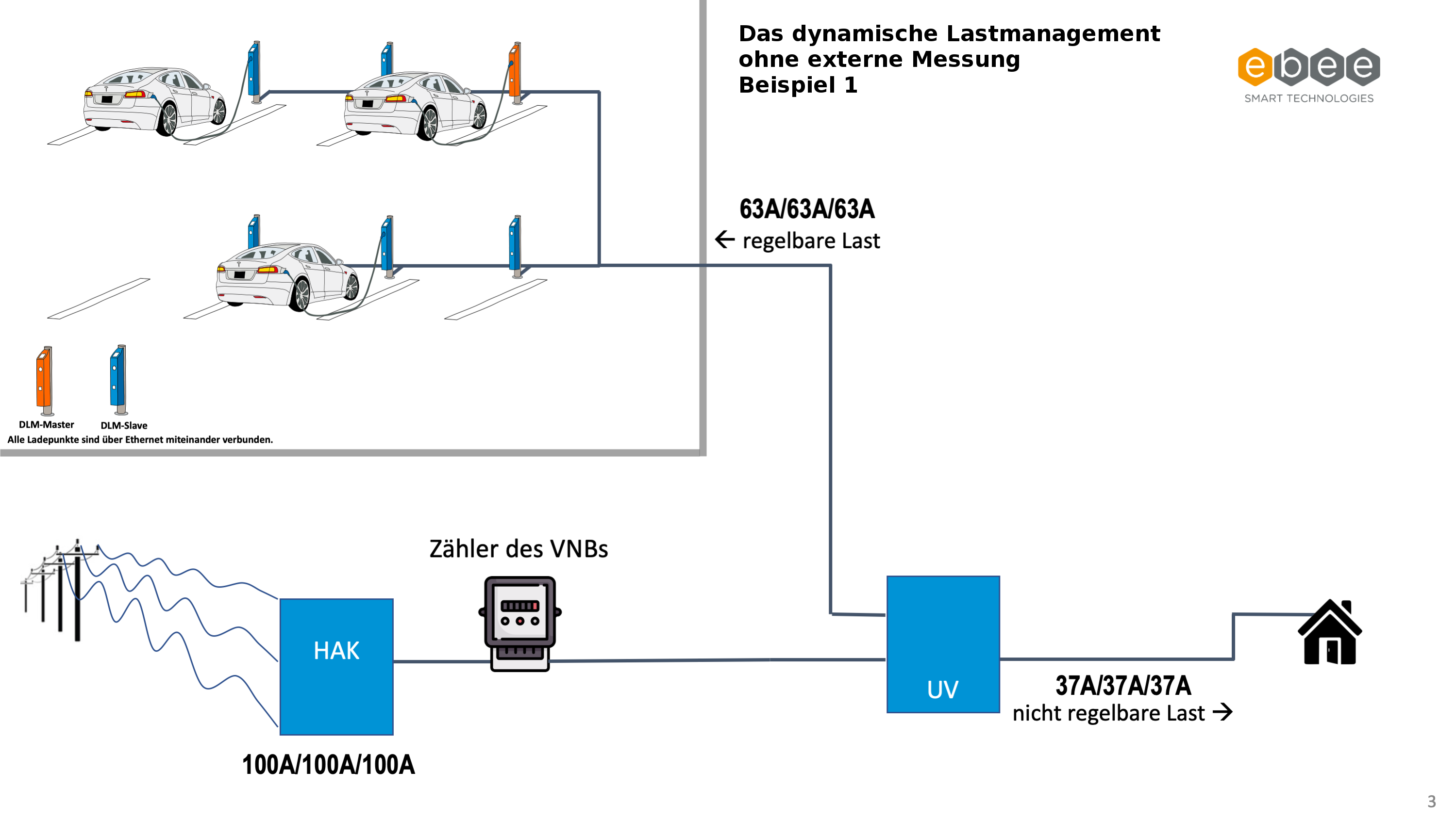
Use case: Load management without external measurement
Here, a fixed upper limit of the current to be distributed is known and set. The load management only requires the instantaneous charging currents of the charging points. A fixed value of the current (for example 63 A) is assigned to the group of charging points. The 63 A is distributed to the charging points on a phase-individual basis. The following two scenarios are intended to illustrate where the use of such load management makes sense:
- A house connection with 100 A supplies a building and the charging infrastructure.
- The UV of the building has a total of 100 A available. The max. load of the building is known, 37 amps (incl. reserve/headroom) must be reserved for this. The charging infrastructure is allocated the remaining 63 A via the DLM and distributed there by the load management among the charging points.
- A house connection with 63 A
- A parking lot or parking garage has its own dedicated house connection for the charging points. There are no other consumers at this house connection besides the charging points.
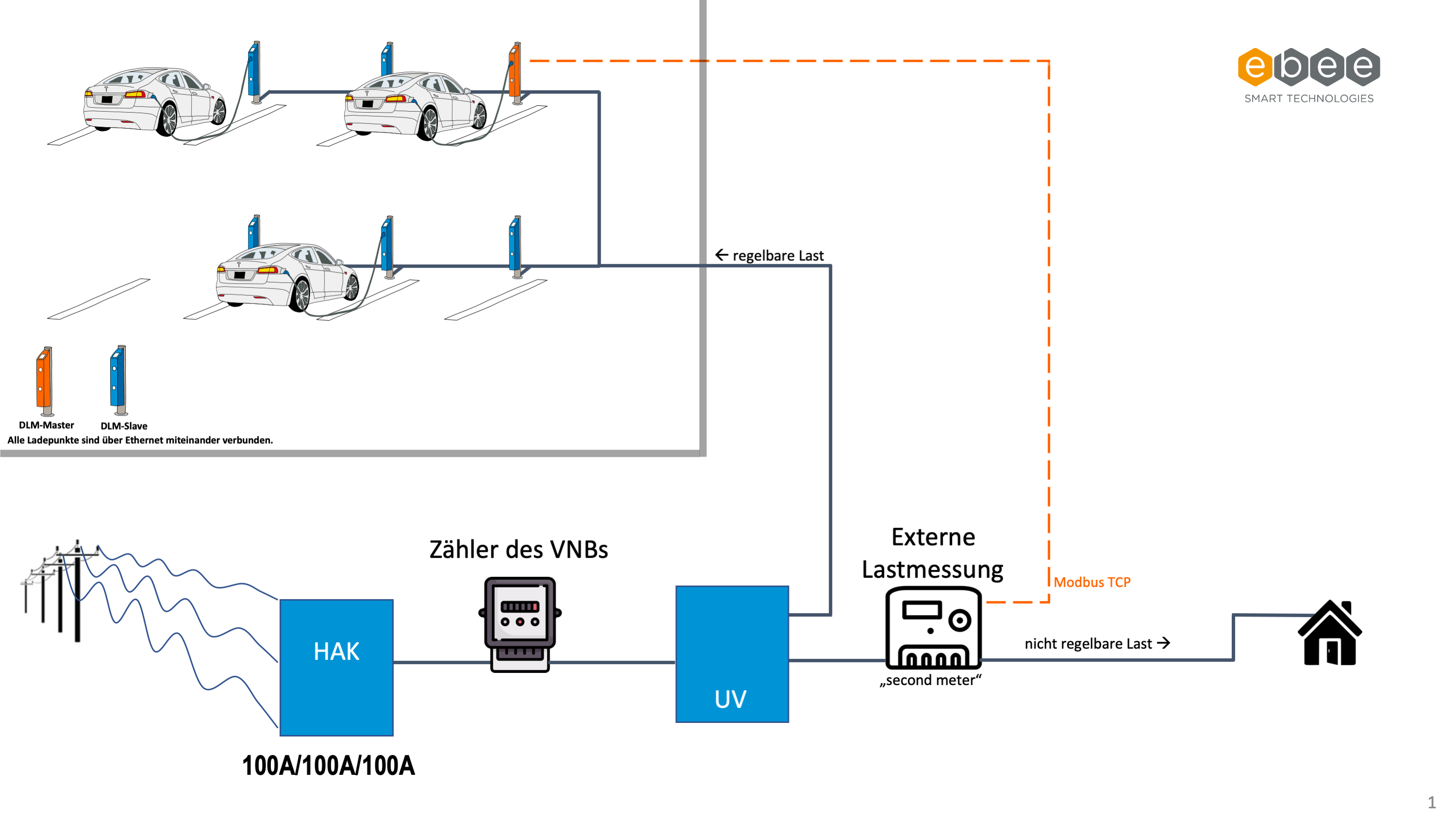
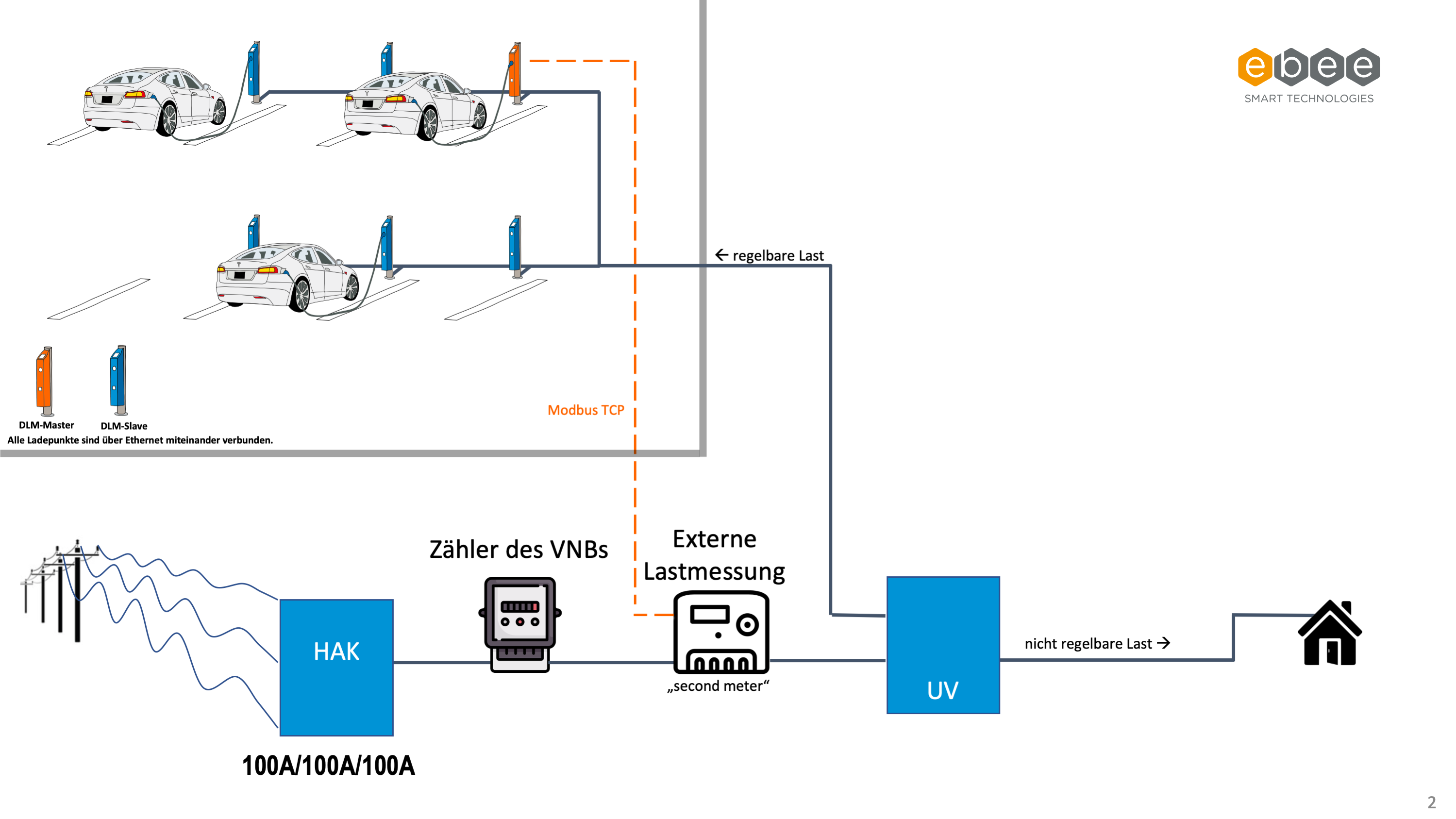
Use case: load management with external measurement.
Here, the DLM must know the total load at the house connection, i.e. not only the current charging currents of the charging points but also the current that is currently flowing through other consumers. This means that the total current to be distributed to the LP can be dynamically adjusted. The "consumption" of the building trust is not known and loads can change. The charging points, or the DLM, must respond to these sometimes spontaneous and uncontrollable load changes. Often there are also HAK that would not allow the additional connection and operation of charging stations due to the design "on paper". No fixed power can be reserved for the charging technology. However, since the load of the buildings is also not always the same, such "load valleys" and reserves can be measured with a continuous power or load measurement at the HAK. And be delivered to the charging stations by the DLM. The charging current of an electric vehicle is controllable and the maximum available charging current is specified to the vehicle by the Charging Station. Taking this specification into account, the vehicle controls its maximum charging current. Depending on the charging time and the degree of filling of the battery, the maximum possible power of the Charging Station of e.g. 11 kW or 22 kW is rarely exhausted. The load management takes this into account and can therefore distribute the surplus to other charging points. The additional meter required in this scenario can be installed directly behind the grid operator's meter (Including EVSE Sub-Distribution) or in the sub-distribution behind the branch of the charging points (Excluding EVSE Sub-Distribution). This is also partly dependent on the installation conditions or the design of the UV. Thus, the load of the additional consumers can be measured and included in the calculation of the DLM.
The following pictures ((HAK: house connection box; UV: sub-distribution; VNB: distribution network operator)) illustrate the setup:
Load Management with External Meter Support (DLM).
Excluding EVSE Sub-Distribution (Recommended Variant).
Including EVSE Sub-Distribution
Phase-specific load management
What does phase individual mean?
A rechargeable electric vehicle usually has a so-called "on-board charger". This charger, which is permanently installed in the car, is connected to a suitable Charging Station by means of a cable. The on-board charger is usually single-phase or three-phase. Thus, in a three-wire network (three-phase current or power current), either one phase (outer conductor) or three phases are loaded.
The charging current communicated by the Charging Station always applies to all phases, regardless of whether the vehicle loads only one or several phases.
Competitor load management systems often assume that all phases are always equally loaded, regardless of the actual load on each phase. Thus, at a Charging Station where a vehicle is charging single phase at 1 x 16 amps, the remaining 2 phases are also reserved at 16 amps each, even though the second and third phases are not actually loaded. The DLM has automatic detection of whether the connected vehicle is loading the grid with single-phase or three-phase. If it is a vehicle with a single-phase charger, the load is reserved only on the corresponding phase, the rest remains available for other charging guests. In this case, any phase rotation is also taken into account. For more details see the chapter "Phase rotation of the ChargePoint".
Unbalanced load
What does unbalanced load and unbalanced load avoidance mean?
Many network operators in Germany are required by their technical connection conditions (TAB) not to allow the apparent power of a phase to exceed 4.6 kVA compared to the two neighboring phase conductors. This means; single-phase loads may draw a maximum current of 20 amps in total if the other two phases are not loaded. Thus, a skew load occurs when in a three-wire system one phase conductor is loaded by more than 20 amperes than the other two phase conductors.
| Example 1 | L1⇒10 A | L2⇒15 A | L3⇒20 A |
|---|---|---|---|
| No difference between all outer conductors by more than 20 amperes. Thus, there is no violation of the maximum allowed asymmetry. | |||
| Example 2 | L1⇒10 A | L2⇒15 A | L3⇒36 A |
| L3 is loaded 21 Amps more than L2 and 26 Amps more than L1. As a result, the max. permissible unbalanced load of 20 A is exceeded. | |||
Mainly due to different charging behavior of electric vehicles, for example, at a 3 x 32 amp Charging Station a single-phase car can charge with more than 20 amps. Although the current signaled by the Charging Station applies to all phases, no information is exchanged between the phase number of the on-board charger from the vehicle and the phase number of the Charging Station. This can lead to an unauthorized unbalanced load. In addition, charging points cannot be set up that offer single-phase charging currents of more than 20 amps. For example, a Charging Station with 1 x 32 amps ≈ 7.4 kW that would enable faster charging speed for cars with stronger single-phase on-board chargers; for example, Opel Ampera-e, Nissan e-NV200, and partially BMW i3. Bender / ebee's load management has a solution for this. As part of the load management, "Current Imbalance Prevention" can be activated. This feature checks if there is an asymmetry between the three phases of more than 20A. The maximum allowed asymmetry can be specified in amps.
The system's skew load limit takes into account all charging points included in the load management. Since the asymmetry must be maintained at the house connection or grid transfer point, single-phase loads of over 20 amps may well be permissible. For example, three vehicles can charge using a single-phase 32 amp on-board charger without violating the maximum skew load by each vehicle charging on a different phase. Which vehicle charges on which phase is detected by the load management system and can thus adjust the allowed charging current. In such a system, charging points with 1 x 32 amperes are possible or, in the case of 3 x 32 amperes charging points, the unbalanced load is limited.
Phase rotation
What does Phase rotation of the ChargePoint mean?
Charge points are usually designed with one or three phases. This means that a car can charge at such charging points via the phase conductor L1 (single-phase) or via the phase conductors L1 L2 L3 (three-phase). The phase relation to each other is always 120°. In order for the load management to optimally distribute the charging current and avoid unbalanced loads, the information of the phase position or phase rotation must be set or communicated for each Charging Station. In order to be able to distribute loads better, the phases are rotated in the subdistribution. Example:
Charging Station 1
| Charging Station | Network |
|---|---|
| L1 ⇒ | L1 |
| L2 ⇒ | L2 |
| L3 ⇒ | L3 |
Charging Station 2
| Charging Station | Network |
|---|---|
| L1 ⇒ | L2 |
| L2 ⇒ | L3 |
| L3 ⇒ | L1 |
Charging Station 3
| Charging Station | Network |
|---|---|
| L1 ⇒ | L3 |
| L2 ⇒ | L1 |
| L3 ⇒ | L2 |
This rotation is done in order to distribute the load generated by single-phase charging cars as evenly as possible to all phases. The parameter "Phase rotation of the ChargePoint" is set in the Charging Station itself as the installer has intended for this Charging Station.
As an example, you can read in the linked document how the phase rotation is recommended for the Charging Station "Berlin".
{{ :wiki:power:phaserotation.pdf | phaserotation}}
Time-dependent load management
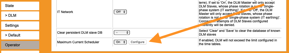
The "Maximum Current Scheduler" function.
In addition to the function of load management without or with an external metering, there is another function to (semi-)dynamically control the load management without external metering.
The function 'Maximum Current Scheduler' allows to determine the parameters of the 'Operator EVSE Sub-Distribution Limit' via a time table depending on the time of day.
With a known and recurring load profile, the charging currents can thus be increased or decreased at times when sufficient reserves are always available. For example, in a single-family home where 60% reserve is always available at the house connection at night, the available charging currents could be ramped up at exactly these times.
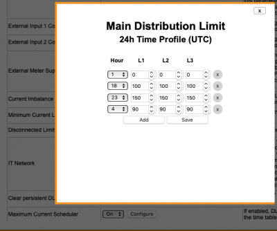
The 24h Time Profile (UTC) can be configured by clicking on "Configure".
At least two entries are necessary. The set currents are always valid from the set time. That means, from the entered time to the next following time this charging current is valid for the DLM. This also applies if the times are not displayed in chronological order. In the example on the right, this means that no charging current is available from 1 o'clock to 4 o'clock. Here it does not matter that the time point '1 o'clock' is at the top and the time point '4 o'clock' is at the bottom.
The times are entered according to Coordinated Universal Time (UTC). The time in Germany is therefore in winter one hour later UTC + 1 = CET - Central European Time and in summer two hours later UTC + 2 = CEST - Central European Summer Time.
The fully resolved and chronologically ordered ({{ :lastmanagement:time_table2.png?400&linkonly|Example "Time Profile"}}) would translate into the following table:
| Time: from - to | DLM Current Limit (L1/L2/L3) |
|---|---|
| 01:00 - 04:00 | 0/0/0 |
| 04:00 - 18:00 | 90/90/90 |
| 18:00 - 23:00 | 100/100/100 |
| 23:00 - 01:00 | 150/150/150 |
Failure cases
DLM master failure
Possible causes leading to failure of the master:
- Voltage drop at the charge controller hosting the DLM Master software.
- Connection failure to the network (LAN, WLAN, GSM, USB) at the Charging Station hosting the DLM Master.
The occurrence of the above events can be circumvented by running the DLM Master software on a charge controller that is operated separately in a distribution cabinet or in a network installation. This charge controller is then operated as a stand-alone variant and does not control a Charging Station. The voltage supply via the low-voltage subdistribution or network installation minimizes the probability of voltage failure and the connection to the network.
In case of voltage drop
If the power supply to the charge controller hosting the DLM Master software fails, the DLM Slaves will fall back to their individually set //Disconnected Limit [A]//. The charge currents will then be static. In sum, the disconnected limits of the DLM slaves should not exceed the value of the maximum available current.
A voltage drop at that Charging Station, which hosts the DLM Master Software, can usually not occur at charging points compliant with calibration law due to a fault at the vehicle or due to poor operation of the charging guest. This is due to the fact that the charge controller has a separate power supply. This means that the DLM Master software can still be operated if an RCD/MCB (FI/LS) has been triggered by the vehicle.
In case of connection failure
In case of an interruption of the network connection of the charge controller hosting the DLM Master Software, the DLM Slaves will behave analogous to the voltage drop. Once the network connection is re-established, the system will automatically recover and be controlled again by the DLM Master.
Failure of the DHCP server
In the event of a DHCP server failure, the network will initially continue to function. Until the validity period [leasetime] expires, all charge points will continue to communicate.
| Version | validity period (leasetime) |
|---|---|
| v4.63 | 12 hours |
| v5.11 | 7 days (168 hours) |
After expiration, it may fall back to the disconnection limit charging current.
If the DHCP server has been activated on the charge controller, which also hosts the DLM master, there is a high probability that the DLM master has also failed. In this respect, the failure of the DHCP server is secondary, as the failure of the DLM master is the more serious failure. Fixing the DLM master failure will most likely fix the DHCP server failure as well.
Recommendation for positioning the DLM master, DHCP server, WAN router.
As described in [[Load management # DLM master failure|DLM master failure]], it may make sense not to run the DLM master, WAN router, or DHCP server on a load controller that is itself a load point. The easiest way to operate an additional charge controller is outside the parking lot. For example, in the network or electrical distribution of the charging points. However, if this is not possible, the question of the optimal Charging Station to run the services arises. Depending on the topology of the parking lot, which has several charging points, the Charging Station with the shortest supply line is ideal, since here the plug of the line, which could be damaged, is the lowest. However, this applies to distributions that are built in a star. If the charging points are connected according to the "daisy-chain" principle, the shortest supply line is not necessarily a guarantee for fail-safety. Depending on the structure, the "middle" Charging Station could supply more charging points with its services in the event of a fault than the "first" or "last" Charging Station in the chain. Furthermore, it can make sense to operate the services 'DHCP Server', 'DLM Master' and 'WAN Router' on different charge controllers.